Rigging a Hand and a Foot
From the original tutorials written by Lyubomir Kovachev
The Hand
Setting up a hand for animation is a tricky thing. The gestures, the movements of wrists and finders are very important, they express emotional states of the character and interact with other characters and objects. That's why it's very important to have an efficient hand setup, capable of doing all the wrist and fingers motions easily. Here is how I do it:
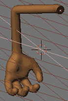
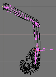
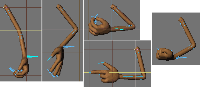
We'll use a simple cartoony arm mesh in this tutorial (Figure 12).
The following setup uses one IK solver for the movemet of the whole arm and 4 other IK solvers for each finger. The rotation of the wrist is achieved by a simple FK bone.
OK. Take a look at the arm mesh and let's start making the armature.
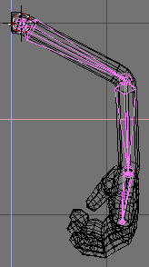
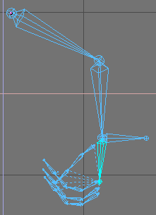
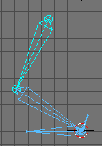
Position the 3D cursor in the shoulder, go to front view and add an armature. Make a chain of 3 bones - one in the upper arm, the second one in the lower arm and the third one should fit the palm, ending at the beginning of the middle finger. This is called an chain of bones. (Figure 13).
Now change the view to side view and deit the bones so that they fit in the arm and palm properly (Figure 14 (Figure 15).
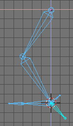
Zoom in the hand and position the cursor at the root of the bone, positioned in the palm. Add a new bone, pointing right, with the same lenght as the palm bone. This will be the IK solver for the arm. (Figure 16).
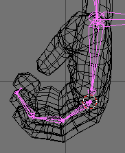
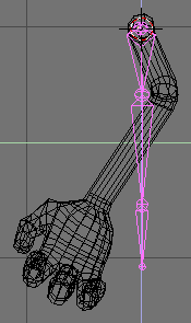
Position the 3D cursor at the beginning of the middle finger and in fron view start building a new chain, consisting of 4 bones (Figure 17). 3 of them will be the actual bones in the finger, and the fourth bone will be a null bone - this is a small bone, pointing to the palm, that will help turning the whole chain to an IK chain later.
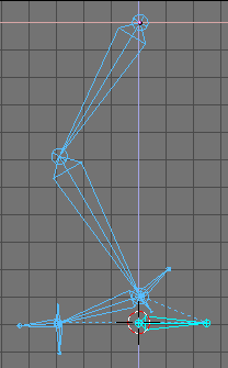
Again, change to side view and re-chape the bones so that they fit the finger well. It could be a tricky part and you may also view the scene using the trackball while reshaping the bones (Figure 18).
Now add the IK solver for this finger chain. Position the 3D cursor at the beginning of the null bone and add bone with the lenght of the other three bones in the finger (Figure 19).
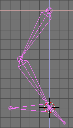
Repeat the same for the creation of the IK chains for the other three fingers. The only difference with the thumb is that it has two actual bones, instead of three. You can just copy and paste the chain and just reshape, reshape, reshape... (Figure 20).
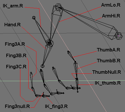
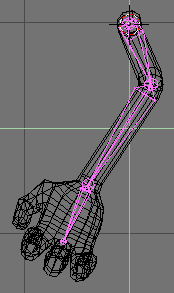
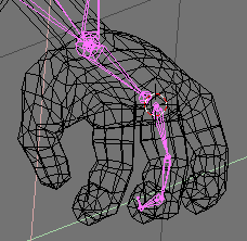
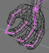
The time has come for the boring part - naming of the bones. You cannot skip this, because you'll need the bone names in the skinning part later. Bones are named as in Figure 21.
Note: The names of the bones of finger 1 and finger 2 are not shown here. They are identical to the names of the bones of finger 3, only the number changes.
Now let's do some parenting.
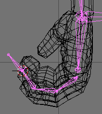
Select the root thumb bone "ThumbA.R" (Figure 22) and in the edit menu click in the "child of" field and choose "Hand.R". You've just parented the thumb bone chain to the hnad bone.
By repeating the same process parent the following bones (Figure 23):
"Fing1A.R" to "Hand.R"
"Fing2A.R" to "Hand.R"
"Fing3A.R" to "Hand.R"
"IK_thumb.R" to "Hand.R"
"IK_fing1.R" to "Hand.R"
"IK_fing2.R" to "Hand.R"
"IK_fing3.R" to "Hand.R"
Why did we do all this? Why did we parent so much bones to "Hand.R"? Because when you rotate the hand (i.e. "Hand.R") all the fingers will follow the hand. Otherwise the fingers will stay still and only the palm will move and you'll get very weird result.
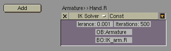
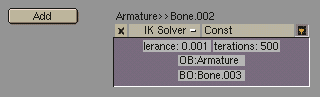
Time to add constraints. Enter pose mode (Figure 24) and open the "Constraints" menu. Choose "Hand.R" and add an IK solver constraint. In the "OB" field type the object name: Armature. The bone went to the center of the armature, but we'll fix this now. In the new "BO" field, that appeared in the constraint window, type the bone name "IK_arm.R". This will be the IK solver bone controlling the arm motion (Figure 25).
Now by repeating the same:
select "ThumbNull.R" and add IK solver "IK_thumb.R",
select "Fing1null.R" and add IK solver "IK_fing1.R",
select "Fing2null.R" and add IK solver "IK_fing2.R",
select "Fing3null.R" and add IK solver "IK_fing3.R".
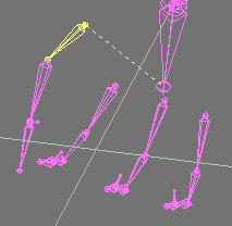
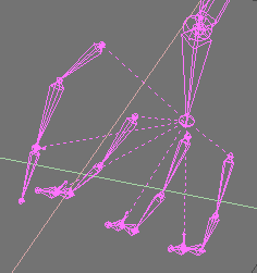
You're finished with the bone part. In pose mode select different IK solvers and move them to test the IK chains. Now you can move the fingers, the thumb, the whole arm and by rotating the "Hand.R" bone you can rotate the whole hand.
So let's do the skinning now. It's the part when you tell the mesh how to deform. You'll add vertex groups to the mesh. Each vertex group should be named after the bone that will deform it. If you don't assign vertex groups, the deformation process will need much more CPU power, the animation process will be dramatically slowed down and you'll get weird results. It's highly recommended (almost mandatory) that you use subdivision surfaces meshes for your characters with low vertex count. Otherwise if you use meshes with lots of vertices, the skinning will be much more difficult. Don't sacrifice detail, but model economically, use as less vertices as possible and always use SubSurf.
Parent the Mesh to the Armature, int the Pop-Up select Armature and in the following select Name Groups. Youre Mesh will be enriched by empty Vertex Groups.
Select the arm mesh, enter edit mode and open the edit buttons window. Notice the small group of buttons with the word "Group" on top. Thanx to the automatic naming feature you have already all the groups you needed created. (Figure 26).
Actually the automatic Grouping scheme has created vertex groups also for the "IK" and "null" bones. These are useless and you can safely delete. Otherwise you can ask Blender not to create Groups at all and create them by yourself before skinning.
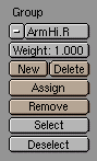
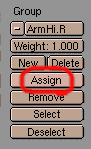
Now let's do the tricky part: Select the vertex group "ArmHi.R" from the edit buttons by clicking on the small button with the white minus sign. Now look at the 3D window. Select all the vertices that you want to be deformed by the "ArmHi.R" bone. (Figure 27).
Now press the "Assign" button in the edit buttons window (Figure 28). You've just added the selected vertices to the "ArmHi.R" vertex group. These vertices will be deformed by the "ArmHi.R" bone.
Repeat the same steps for the other vertex groups: select vertices and assign them to the corresponding group. This is a tricky process. Do it carefully. If you've assigned some vertices to a certain group by mistake, don't worry. Just select the unneeded vertices and press the "Remove" button. You can add a vertex to more than one vertex group. For example the vertices that build joints (of fingers, wrist, elbow, etc.) could be assigned to the two vertex groups that are situated close to it. You can also assign vertices to deform with different strength. The default stregth is 1.000, but you can add vertices with strength 0.500 or less. The l ower the strength value, the less deformation for that vertex. You can make a vertex deform 75% by one bone and 25% by another, or 50% by one and 50% by another. It's all a matter of testing the deformation until you achieve the result you want. In general if your arm model has half-flexed joints (as the model in this tutorial you will get good results without using strenght values different than 1.000. My own rule of thumb when modelling a character is: always model the arms fingers and legs half-flexed, not straight. This is a guarantee for good deformation.
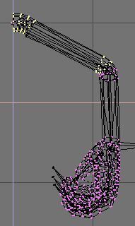
When you're finished adding vertices to vertex groups, exit edit mode and parent the arm to the armature. If you haven't made any mistakes now you'll have a well set up arm with a hand. Select the armature, enter pose mode, select the different IK solvers and test the arm and fingers (Figure 29).
The Foot
The setup of legs and feet is maybe the most important thing in the whole rigging process. Bad foot setup may lead to the well known "sliding-feet" effect, which is very annoying and usually ruins the whole animation. A well made complex foot setup must be capable of standing still on the ground while moving the body, and doing other tricky stuff like standing on tiptoe, moving the toes, etc. Now we're going to discuss several different foot setups that can be used for different purposes.
First let's see how a bad foot setup looks like (Figure 30).
Start building a bone chain of three bones - one for the upper leg, the second one for the lower leg and the third one for foot. Now move the 3D cursor at the heel joint and add another bone - this will be the IK solver. Now add that bone as an IK solver constraint to the foot bone. (Figure 31).
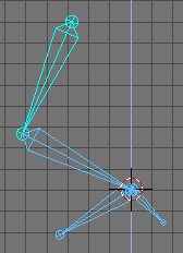
Test the armature: in pose mode grab the IK solver and move it - it's moving OK. Now grab the first bone in the chain (the upper leg) and move it. The foot is moving too and we don't want this to happen! (Figure 32).
Usually in an animation you'll move the body a lot. The upper leg bone is parented to the body and it will be affected by it. So every time you make your character move or rotate his body, the feet will slide over the ground and go under it and over it. Especially in a walkcycle, this would lead to an awful result.
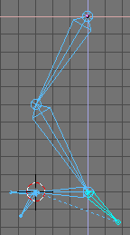
Now maybe you think this could be avoid by adding a second IK solver at the toes (Figure 33). Let's do it. Start a new armature. Add a chain of four bones: upper leg, lower leg, foot and toes. Add two IK solvers - one for the foot and one for the toes. Parent the toe IK solver bone to the foot IK solver bone.
Test this setup - grab the upper leg bome and move it (Figure 34). Well, now the sliding isn't so much as in the previous setup, but it's enough to ruin the animation.
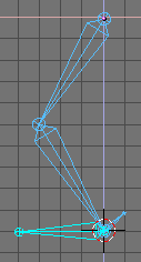
Start a new armature. Make a chain if three bones - upper leg, lower leg and a null bone. The null bone is a small bone, that we'll add the IK solver to. Now position the 3D cursor at the heel and add the foot bone. Now add the foot bone as an IK solver constraint to the null bone (Figure 35).
(You can also add another bone as an IK solver and add a "copy location" constraint to the foot bone, with the IK solver as target bone.)
Test this - now it works. When you move the upper leg the foot stands still (Figure 36). That's good. But still not enough. Move the upper leg up a bit more. The leg chain goes up, but the foot stays on the ground. Well, that's a shortcoming of this setup, but you're not supposed the raise the body so much and not move the IK solver up too during animation...
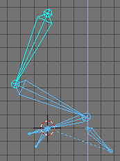
Again, build a chain of three bones - upper leg, lower leg and null bone. Position the 3D cursor at the heel and add a chain of two bones - the foot bone and the toes bone. Now add an IK solver to the foot bone (Figure 37).
Test it. This is a good setup with stable, isolated foot and moving toes. But you still cannot make standing on tiptoe with this setup.
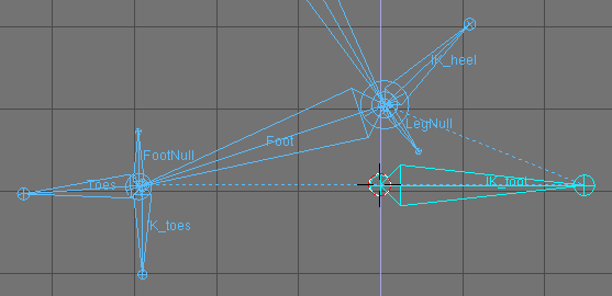
Build a chain of three bones - upper leg, lower leg and null bone (name it LegNull) (Figure 38). Starting at the heel point, make a second chain of two bones only - foot bone (Foot) and a small null bone (FootNull). Position the 3D cursor at the end of the foot bone and add the toes bone (Toes). From the same point create an IK solver bone (IK_toes). Now position the 3D cursor at the heel and add another IK solver there (IK_heel). Finally, starting somewhere near the heel, add a bigger IK solver (IK_foot) (Figure 39).
Now let's add the constraints. Do the following:
To the bone "Toes" add a copy location contraint with target bone "IK_toes".
To "FootNull" - an IK solver constraint (target - "IK_toes")
To "Foot" - copy location (target - "LegNull").
To "LegNull" - IK solver (target - "IK_heel")
Well, that's it. Now test the armature. Grab "IK_foot" and move it up. Now grab "IK_toes" and move it down. The foot changes it's rotation, but it looks like the toes are disconnected from it. But if you animate carefully you'll always manage to keep the toes from going away from the foot. Now return the armature to it's initial pose. grab "IK_heel" and "LegHi" and move them up. Now the character is standing on his tiptoes. The foot may appear disconnected from the toes again, but you can fix the pose by selecting "IK_heel" only and moving it a bit forward or backwards. This setup may not be the most easy one for animation, but gives you more possibilities that the previous setups. Usually when you don't need to make your character stand on tiptoe, you've better stick to some of the easier setups. You'll never make a perfect setup. You can just improve, but there will always be shortcomings. Feel free to experiment and if you invent something better, don't hesitate to drop an e-mail to: lpk3d@yahoo.com.