Rigging Mechanics
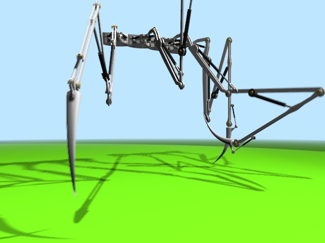
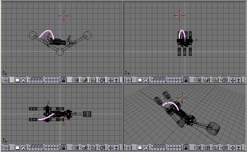
Armatures are great also for rigging mechanical stuff, like robots, warriorMechs etc (Figure 41).
First step is to create the mesh for the arms. We are not here for organic, we are here for mechanics. So no single mesh thing. The arm/leg/whatever is made of rigid parts, each part is a single mesh, parts moves/rotates one with respect to the other.
Although Figure 41 has four spider-like legs arms, each of which have 5 sections, it is clearer to explain the tricks with just a single joint arm.
My suggestion is this, the arm, on the left, made by two equal sections, and the forearm, on the right, made by just one section. Note the cylinders which represents the shoulder (left) the elbow (center) and the wrist (right) (Figure 42).
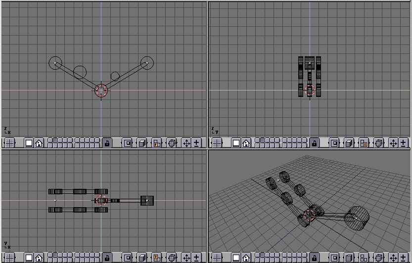
The other cylinders in the middle of the arm and forearm are the places where the piston will be linked to.
Note that it is much easier if the axis of mutual rotation (shoulder, elbow, etc.) are exactly on grid points. This is not necessary though, if you master well Blender Snap menu.
Pivot axis
Then add the mechanical axes in the pivot points. Theoretically you should add one at each joint and two for every piston. For the sake of simplicity here there are only the two axes for the piston, made with plain cylinders (Figure 43).
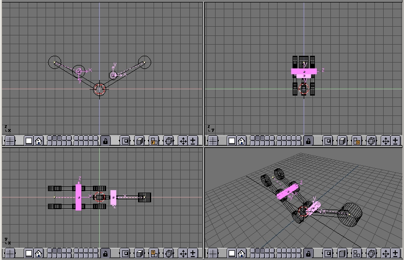
Note two things:
It is fundamental that the center of the mesh is exactly in the middle and exactly on the axis of rotation of the piston
Each axis must be parented to the pertinent arm mesh.
The Armature
Now it is time to set up the armature. Just a two bones armature is enough (Figure 44).
To have an accurate movement, the joints must be precisely set on the pivoting axis (this is why I told you to place such axes on grid points before, so that you can use the Move Selected To Grid feature)
Name the bones smartly (Arm and Forearm, for example). Parent the Arm Mesh to the armature, selecting the 'Bone' option and the Arm bone. Do the same with the forearm mesh and forearm bone.
 | Parent to Bone |
|---|---|
Parent to bone effectvely makes the Object follow the bone without any deformation. This is what should happen for a robot which is made by undeformable pieces of steel! |
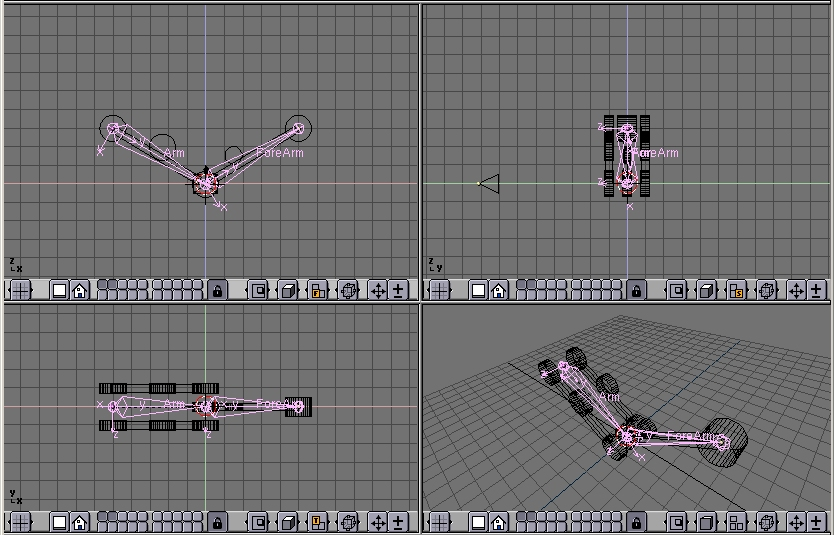
If you switch to pose mode you can move your arm by rotating the bones. (Figure 45). You cann add an IKA solver as we did in the previous section if you like.
Hydraulics
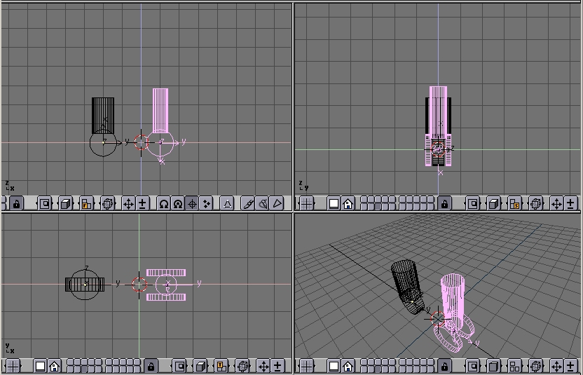
Make a piston with two cylinders, a larger one and a thinner one, with some sort of nice head for linking to the pivoting points (Figure 46).
It is is MANDATORY for the two pieces to have the mesh center exactly on the respective pivoting axis.
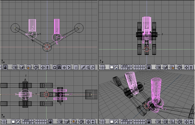
Place them in the correct position and parent each piston piece to the pertinent mesh representing the axis. (Figure 47).
If you now rotate the two pieces in the position they should have to form a correct STILL image you get a nice piston. (Figure 48, left).
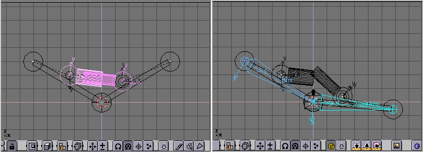
But if you switch to pose mode and start moving the Arm/Forearm the piston gets screwed up... (Figure 48, right).
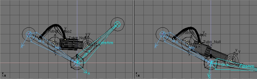
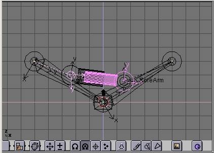
To make a working piston you must make each half pison track the other half piston's pivot axis This is why the position of all the mesh centers is so critical (Figure 49).
Select half a piston, select the other half piston's axis mesh, press CTRL-T. Beware, this might bring to very funny results. You must experiment with the various track button in the Animation (F7) window. The buttons top left TrackX,Y... and pay attention to the axis of the meshes (Figure 50).
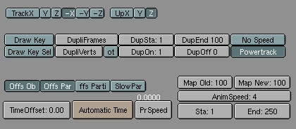
Remember also to press the 'PowerTrack' button for a nicer result (Figure 50).
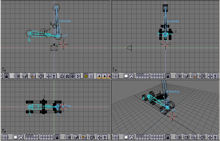
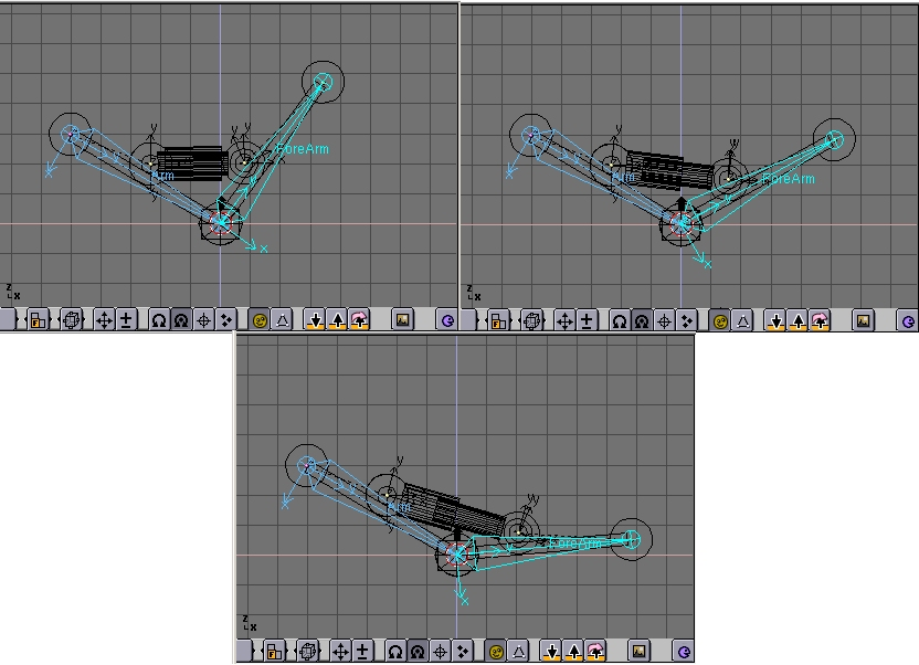
Now, if you switch to pose mode and rotate your bones the piston will extend and contract nicely, as it should in reality. (Figure 51).
Next issue now is, since pistons work with pressurized oil which is sent into them, for a really accurate model I should add some tubes. But how to place a nicely deforming tube going from arm to piston? The two ends should stick to two rigid bodies reciprocally rotating. This requires IKA!
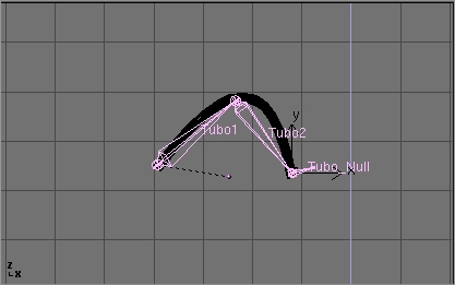
First add a mesh in the shape of the tube you want to model (Figure 52).
Personally I prefer to draw the tube in its bent position as a beveled curve.
This is done by adding a Bezier curve, adding a Bezier circle, and using the Bezier circle as BevOb of the Bezier curve. Then convert that to a mesh ALT-C to be able to deform it with an armature.
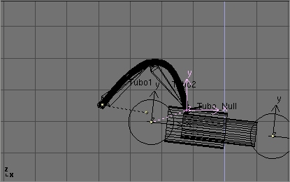
Then add an armature. A couple of bones are enough. This armature should go from the tube 'fixed' end to the tube 'mobile' end. Add a third bone which will be used for the Inverse Kinematic solution (Figure 53).
Be sure that the armature is parented to the object where the 'fixed' part of the tube is, well, fixed. In this case the robot arm. Add also an Empty at the 'mobile' end of the tube. (Figure 54).
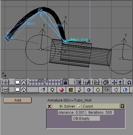
Parent the Empty to the 'mobile' part of the structure. In this case the outer part of the piston to which the tube is linked. In pose mode go to the 'Constrains' window (chain icon). Select the last bone, the one which starts from where the tube ends, and Add a constrain. Select the 'IK solver' type of constrains and Select the newely created Empty as target Object 'OB:'. (Figure 55). You can play with Tolerance and Iterations if you like.
Lastly, parent the tube to the Armature via the 'Armature' option. Create Vertex groups if you like. Now if, in pose mode, you move the arm, the two parts of the piston keeps moving appropriately, and the Empty follows. This obliges the IKA Armature of the tube to move, to follow the Empty, and, consequently, the Tube to deform (Figure 55).