Building the body
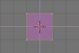
Turn to the front view with NUM1 and add a cube by pressing SPACE and selecting menu ADD, submenu Mesh, sub-submenu Cube. In the following exercises we will write SPACE>>ADD>>Mesh>>Cube as shorthand for these kind of actions. A cube will appear (Figure 4). A newly added mesh is in a particular mode called EditMode in which you can move the single vertices that comprise the mesh. By default all vertices are selected (Yellow), all edges selected (Dark Yellow) and all faces selected (Pink).
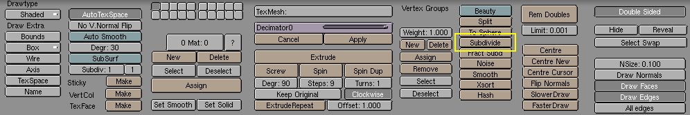
We will call the Gingerbread man "Gus". Our first task is to build Gus' body. This will be done by working on our cube in EditMode with the set of tools Blender provides. To have a look at these tools push the button which has a square with yellow vertices in the Button Window (Figure 5). There is a keyboard shortcut for this, F9.

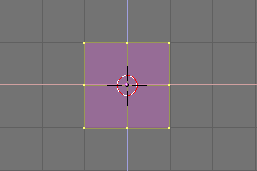
Now locate the Subdivide button and press it once (Figure 6). This will split each side of the cube in two, creating new vertices and faces (Figure 7).
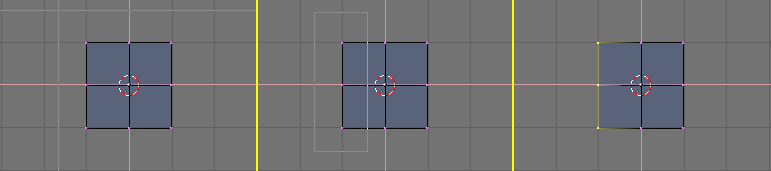
With your cursor hovering on the 3D window press AKEY. This will de-select all. Vertices will turn Pink, edges Black and faces Blue. Now press BKEY. The cursor will change to a couple of orthogonal gray lines. Go above and to the left with respect to the cube, press LMB and, while keeping it pressed, drag the mouse down and to the right so that the gray box which appears encompasses all the leftmost vertices. Now release the LMB. This sequence, which let you select a group of vertices in a box, is summarized in Figure 8.
 | Box Select |
|---|---|
In many occasions there may be vertices hidden behind other vertices. This is the case here, our subdivided cube has 26 vertices, yet you can only see nine because the others are hidden. A normal RMB click selects only one of these stacked vertices, whereas a Box select selects all. Hence, in this case, even if you see only three vertices turning yellow you have actually selected nine vertices. |
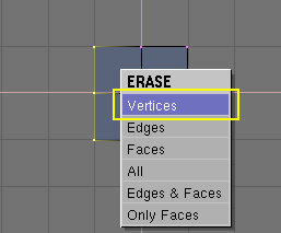
Now press XKEY and, from the menu that pops up, select Vertices to erase the selected vertices (Figure 9).
| Undo |
|---|---|
Beware, for performance issues Blender does not have an Undo function, at least not the one everyone thinks of as an Undo function. In any case, this is not a great issues as there are many mechanisms to recover from mistakes. One of these is the Mesh Undo function. This works only in EditMode and returns the mesh to the state it had when EditMode was entered. You can switch in and out of EditMode by pressing TAB. You might wish to switch out of EditMode every time you do one of our modelling steps correctly, and then switch back in. And press UKEY to turn back to the last correct mesh if necessary. Also, pressing ESC in the middle of an action cancels the action, reverting to the previous state. We will cover other Undo methods later. |
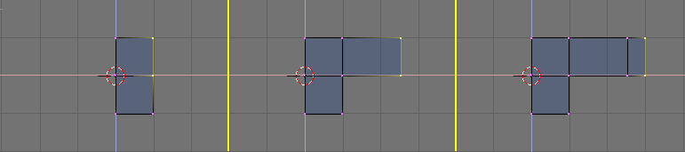
Now, with the sequence you just learned, Box Select the two topmost vertices (Figure 10, left). Press EKEY and click on the Extrude menu entry which appears to extrude them. This will create new vertices and faces. The newly created vertices are free to move and will follow the mouse. Move them to the right.
To constrain the movement horizontally or vertically you can click MMB while moving. The movement will then be constrained horizontally if you were moving more or less horizontally, or vertically otherwise. You can swich back to unconstrained movement by clicking MMB again.
Move them 1 square and a half to the right, then click LMB to fix their position. Extrude again, via EKEY and move the new vertices another half square to the right. Figure 10 show this sequence.
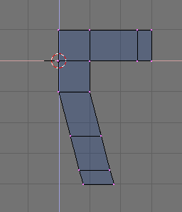
Now Gus has his left arm (he's facing us). We will build the left leg the same way by extruding the lower vertices.
Try to get to something like that shown in Figure 11. Please note that for the leg we used the Extrude tool three times. We don't care of elbows... but we will need a knee later on!
| Coincident vertices |
|---|---|
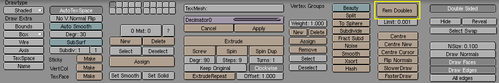
If you extrude and, in the moving process you change your mind and press Esc to recover, the extruded vertices will still be there, in their original location! You can move them again, by pressing GKEY or do whatever you want (scale rotate etc.), but you probably don't want to extrude them again. To fully undo the extrusion look for the Remove Doubles button, highlighted in Figure 12. This will eliminate coincident vertices. |
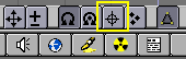
Now it is time to create the other half of Gus, select all vertices (AKEY) and press the 3DWindow toolbar button which resembes a cross-hair (Figure 13). Now, leave the mouse still. Press SHIFT-D to duplicate all selected vertices, edges and faces, SKEY to switch to "Scale" mode, then XKEY followed by either ENTER or a LMB click to flip the duplicate. The result is shown in Figure 14.
De-select all and re-select all by pressing AKEY twice and eliminate the coincident vertices by pressing the Remove doubles button (Figure 12). A box will appear, notifying you that 8 vertices have been removed.
| Reference center |
|---|---|
In Blender, scaling, rotating and other mesh modifications occur either with respect to the cursor position, or the object center or the baricentrum of the selected items, depending on which of the four buttons in the top center group in Figure 13 is active. The cross-hair one selects the cursor as reference. |
| Moving the cursor |
|---|---|
Here we have assumed that the cursor never moved from its original position. As a matter of fact, you move the cursor by clicking LMB in the 3D window. If you need to place the cursor at a specific grid point, as it is in the present case, you can place it next to the desired position and press Shift-S. This brings up the Snap Menu. The entry Curs->Grid places the cursor exactly on a grid point. The Curs->Sel places it exactly on the selected object. The other entries move objects rather than the cursor. |
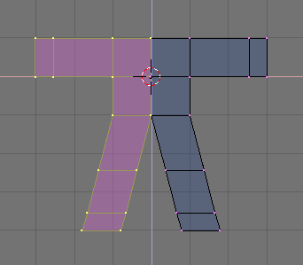
Use what you have just learned about moving the cursor to place it exactly one grid square above Gus' body (Figure 15, left). Add a new cube here (SPACE>>ADD>>Mesh>>Cube). Press GKEY to switch to Grab Mode for the newly created vertices and move them down, constraining the movement with MMB, for about one third of a grid unit (Figure 15, right).
This is a rough figure at best, to make it smoother locate the SubSurf Toggle Button Figure 16 and switch it on. Be sure to set both the two NumButtons below to 2. Switch out of EditMode (TAB) and switch from the current default Wireframe Mode to Solid mode with ZKEY to have a look at Gus. It should look like Figure 17 left. The SubSurf technique dynamically computes a high poly smooth mesh of a low poly coarse mesh.
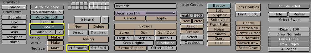
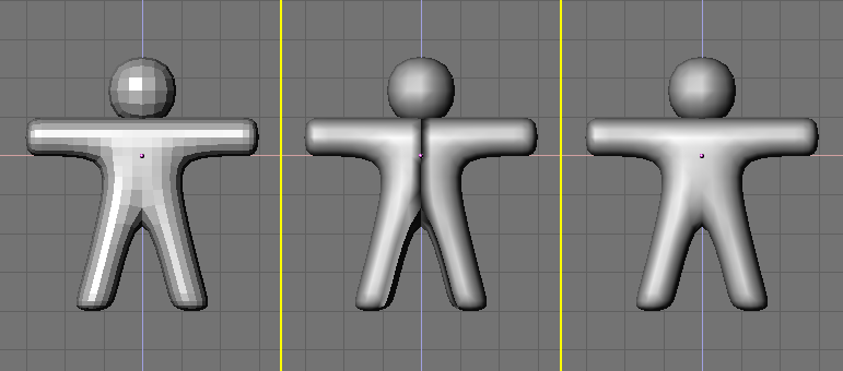
To make it look smooth, press the SetSmooth button in Figure 16. Gus will now be smooth but with funny black lines in the middle (Figure 17, middle). This because the SubSurf is computed using information about the coarse mesh normal directions, and these might not be coherent if extrusions and flippings have been made. To reset the normals, switch back to EditMode (TAB), select all vertices (AKEY) and press CTRL-N. Click with LMB on the Recalc normals outside box which appears. Now Gus will be nice and smooth, as shown in Figure 17, right.
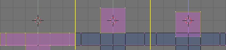
Press MMB and drag the mouse around to view Gus from all angles. He is too thick! Switch to side view NUM3. Switch to EditMode if you are not there already, and back to Wireframe Mode ( ZKEY), and select all vertices with AKEY (Figure 18, left).
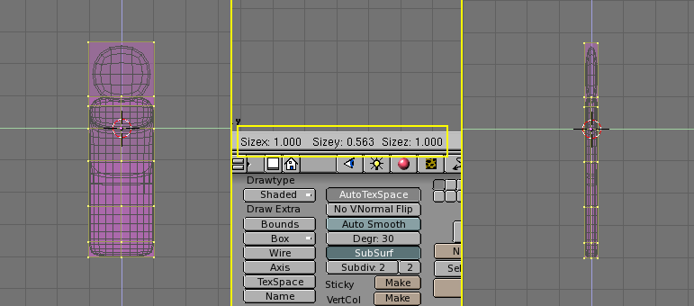
Now, to make Gus thin, press SKEY and start to move the mouse horizontally. Click MMB to constrain scaling to just one axis. If you now move the mouse toward Gus he should become thinner but remain the same height. You should note on the 3DWindow toolbar three numbers giving the scaling factor. After you have clicked MMB only one will vary. Press and keep pressed Ctrl. The scale factor will now vary in discrete steps of value 0.1. Scale Gus down so that the factor is 0.2 and fix the dimension by clicking LMB.
Switch back to Front view and to Solid mode (ZKEY) rotate your view via MMB. Gus is much better!