Radiosity Juicy example
To get definitely away from dry theory and shows what Radiosity can really achieve let's look at an example.
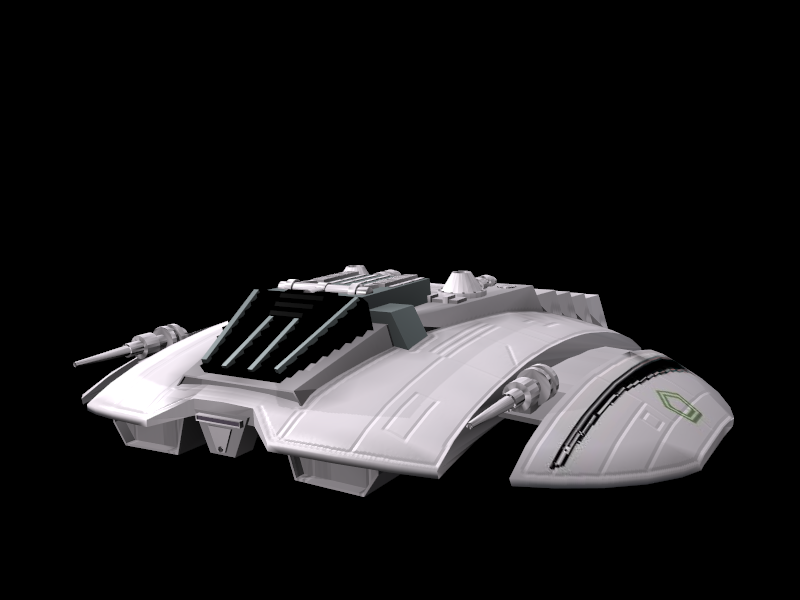
This will actually show you a true Global Illumination scene, with smoother results than the 'Dupliverted Spot Lights' technique shown in the Lighting Chapter to attain something like Figure 8.
Setting up.
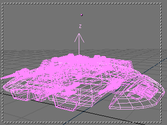
We have only two elements in the scene at start up: a Cylon Raider (if you remember Galactica...) and a camera. The Raider has the default grey material, except for the main cockpit windows which are black. For this technique, we will not need any lamps.
The first thing that we will want to add to the scene is a plane. This plane will be used as the floor in our scene. Resize the plane as shown in Figure 9 and place it just under the Raider. Leave a little space between the plane and the Raider bottom. This will give us a nice "floating" look.
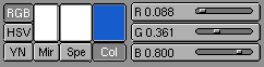
Next, you will want to give the plane a material and select a color for it. We will try to use a nice blue. You can use the setting in Figure 10 for it.
The Sky Dome
We want to make a GI rendering, so the next thing that we are going to add is an icosphere. This sphere is going to be our light source instead of the typical lamps. What we are going to do is use its faces as emitters that will project light for us in multiple directions instead of in one direction as with a typical, single, lamp. This will give us the desired effect.
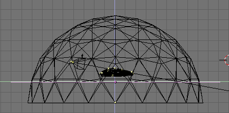
To set this up, add an icosphere with a subdivision of 3. While still in EditMode, use the BKEY select mode to select the lower portion of the sphere and delete it. This will leave us with our dome. Resize the dome to better fit the scene and match it up with your plane. It should resemble Figure 11.
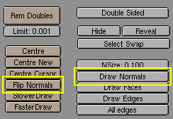
Next, we want to make sure that we have all the vertices of the dome selected and then click on the EditButtons (F9) and select Draw Normals. This allows us to see in which direction the vertices are "emitting". By default it will be outside, so hit the Flip Normals button, which will change the vertex emitter from projecting outward to projecting inward in our dome (Figure 12).
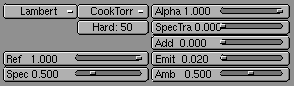
Now that we have created our dome, we need a new material. When you create the material for the dome change the following settings in the MaterialButtons (F5):
Add = 0.000
Ref = 1.000
Alpha = 1.000
Emit = 0.020
The Emit slider here is the key. This setting controls the amount of light "emitted" from our dome. 0.020 is a good default. Remember that the dome is the bigger part of the scene! you don't want too much light! But you can experiment with this setting to get different results. The lower the setting here though the longer the "solve" time later. (Figure 13).
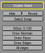
At this point we have created everything that we need for our scene. The next step will be to alter the dome and the plane from "double-sided" to "single-sided". To achieve this, we will select the dome mesh and then go back to the EditButtons (F9). Click the Double Sided button and turn it off (Figure 14). Repeat this process for the Plane.
The Radiosity solution
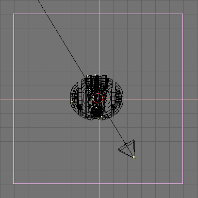
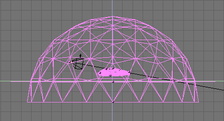
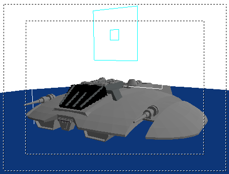
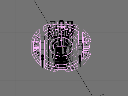
Now the next few steps are the heart and soul of Global Illumination. Go to side view with NUM 3 and use AKEY to select all of the meshes in our scene. Next hold SHIFT and double click on your camera. We do not want this selected. It should look similar to Figure 15.
After selecting the meshes, go to camera view with NUM 0 and then turn on shaded mode with ZKEY so we can see inside our dome.
Now select the Radiosity Buttons
 ). On the left-hand side of the menu, click the
Collect Meshes button. You should notice a change
in your view in the colors. It should look similar to Figure 16.
). On the left-hand side of the menu, click the
Collect Meshes button. You should notice a change
in your view in the colors. It should look similar to Figure 16.
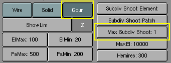
Next, to keep the Raider smooth like our original mesh, we will want to change from Solid to Gour. This will give our Raider its nice curves back, in the same way Set Smooth would in the EditButtons. You'll also need to change the Max Subdiv Shoot to 1 (Figure 17). Do not forget this step!
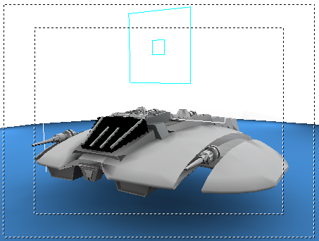
After you have set Gour and Max Subdiv Shoot, click Go and wait. Blender will then begin calculating the emit part of the dome, going face by face, thus "solving" the render. As it does this, you will see the scene change as more and more light is added to the scene and the meshes are changed. You will also notice that the cursor in Blender changes to a counter much like if it were an animation. Let Blender run, solving the radiosity problem.
Letting Blender go to somewhere between 50-500 depending on the scene can do, for most cases. The solving time depends on you and how long you decide to let it run... remember you can hit ESC at any time to stop the process. This is an area that can be experimented with for different results. This can take from 5 to 10 minutes and your system speed will also greatly determine how long this process takes. Figure 18 is our Raider after 100.
After hitting the ESC key and stopping the solution, click Replace Meshes and then Free Radio Data. This finalizes our solve and replaces our previous scene with the new solved radiosity scene.
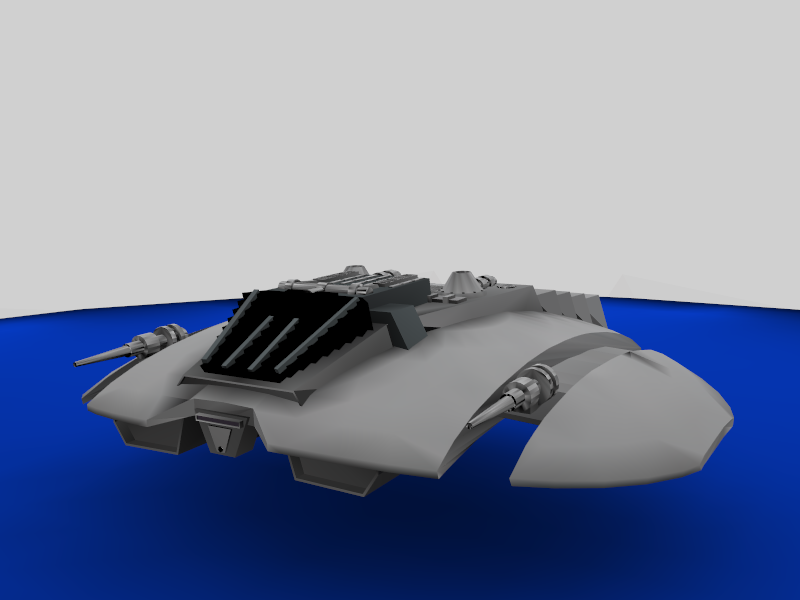
Now we are ready for F12 and render (Figure 19).
Texturing
There you go folks! You now have a very clean looking render with soft 360 degree lighting using radiosity. Very nice... But the next thing we want to do is add textures to the mesh. So go back to our main screen area.
Now try selecting your mesh and you will notice that it selects not only the Raider but the plane and dome as well. That is because Radiosity created a new single mesh through the solution process. To add a texture though, we only want the Raider.
So, select the mesh and then go into EditMode. In EditMode we can delete the dome and plane since they are no longer needed. You can use the LKEY to select the proper vertices and press XKEY to delete them. Keep selecting and deleting until you are left with only the Raider. It should look like in Figure 20. If we were to render it now with F12, we would get just a black background and our Raider. This is nice... but again, we want textures!
To add textures to mesh, we must separate out the areas that we are going to apply materials and textures to. For the Raider, We want to add textures to the wings and mid-section. To do this select the Raider mesh, and go back into EditMode. Select a vertex near the edge of the wing and then hit the LKEY to select linked vertices. Do the same on the other side. Next, click on the mid section of the ship and do the same thing. Select the areas shown in Figure 21. When you have those, hit the PKEY to separate the vertices selected.
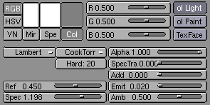
We now have our wing section separate and are ready to add the materials and textures. We want to create a new material for this mesh. To get a nice metallic look, we can use the settings in Figure 22.
Time to add the textures. We want to achieve some pretty elaborate results. We will need two bump-maps to create grooves and two mask for painting and 'decals'. There are hence four textures for the Raider wings to be created, as shown in Figure 23.
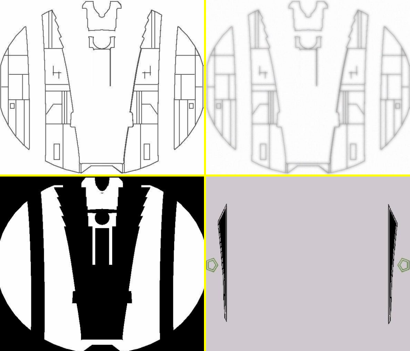
The textures should be placed in four material channels in the rider top mesh. 'RaiderBM' and 'RaiderDI' should be set to a negative NOR (Figure 24a -click NOR twice, it will turn yellow). 'Raider' should be set up as negative REF (Figure 24b).
 | Which material? |
|---|---|
A Mesh coming from a Radiosity solution tipically has more than one material on it. Theright one, the one where to add trtextures is the one callad RadioMat. |
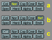
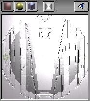
The result is the desired metallic plating for the hull of the Raider. Finally the fourth texture, 'Markings', is set to COL in the MaterialButtons (Figure 24c). This will give the Raider its proper striping and insignia. Our rider is quite flat, so the Flat projection is adequate. Were it a more complex shape some UV mapping would have been required to attain good results. The material preview for the mesh should look like Figure 25.
Our textures to won't show up in the rendering right now (except markings) because Nor and Ref type texture reacts to lighting, and there is no light source in the scene! Hence will now need to add a lamp or two, keeping in mind that our ship is still lit pretty well from the radiosity solve, so lamps energy should be quite weak. Once you have your lamps, you try a test render. Experiment with the lamps until you get the results you like.
The final rendering (Figure 8 in the Section called Radiosity Juicy example) shows a nice well lit Raider with soft texturing.