Radiosity Step by Step
Ok, the quickstart might have been too 'superficial' and you want to get deeper insight! Go on reading.
There are few important points to grasp for practical Radiosity:
Only Meshes in Blender are allowed as input for Radiosity. It is important to realize that each face in a Mesh becomes a Patch, and thus a potential energy emitter and reflector. Typically, large Patches send and receive more energy than small ones. It is therefore important to have a well-balanced input model with Patches large enough to make a difference! When you add extremely small faces, these will (almost) never receive enough energy to be noticed by the "progressive refinement" method, which only selects Patches with large amounts of unshot energy.
 | Non-mesh Objects |
|---|---|
Only Meshes means that you have to convert Curves and and Surfaces to Meshes (CTRL+C) before starting the Radiosity solution! |
You assign Materials as usual to the input models. The RGB value of the Material defines the Patch color. The 'Emit' value of a Material defines if a Patch is loaded with energy at the start of the Radiosity simulation. The "Emit" value is multiplied with the area of a Patch to calculate the initial amount of unshot energy. Textures in a Material are not taken account of.
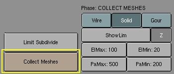
Phase 1: Collect Meshes
All selected and visible Meshes in the current Scene are converted to Patches as soon as the Collect Meshes button is pressed (Figure 3). As a result some Buttons in the interface change color. Blender now has entered the Radiosity mode, and other editing functions are blocked until the button "Free Data" has been pressed. The "Phase" text now says 'Init' and shows the number of Patches and Elements.
| Emitting faces |
|---|---|
Check the number of "Emit:" patches, if this is zero nothing interesting can happen! You need at least 1 emitting patch to have light and hence a solution. |
After the Meshes are collected, they are drawn in a pseudo lighting mode that clearly differs from the normal drawing. The 'collected' Meshes are not visible until Free Radio Data has been invoked at the end of the process.
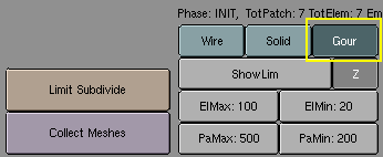
Wire, Solid, Gour (RowBut) Three drawmode options are included which draw independent of the indicated drawmode of a 3DWindow. Gouraud display is only performed after the Radiosity process has started.
Press also the Gour button, to have smoother results on curved surfaces (Figure 4).
Phase 2: Subdivision limits.
Blender offers a few settings to define the minimum and maximum sizes of Patches and Elements (Figure 5).
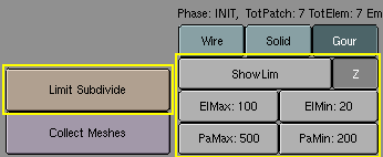
Limit Subdivide (But) With respect to the values "PaMax" and "PaMin", the Patches are subdivided. This subdivision is also automatically performed when a "GO" action has started.
PaMax, PaMin (NumBut)
ElMax, ElMin (NumBut) The maximum and minimum size of a Patch or Element. These limits are used during all Radiosity phases. The unit is expressed in 0.0001 of the boundbox size of the entire environment. Hence, with deafault 500 and 200 settings maximum and minimum Patch size 0.05 of the entire model (1/20) and 0.02 of the entire model (1/50).
ShowLim, Z (TogBut) This option visualizes the Patch and Element limits. By pressing the 'Z' option, the limits are drawn rotated differently. The white lines show the Patch limits, cyan lines show the Element limits.
Phase 3: Adaptive Subdividing
Last settings before starting the analysis (Figure 6).
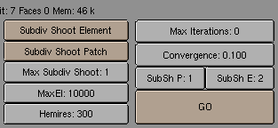
Hemires (NumBut) The size of a hemicube; the color-coded images used to find the Elements that are visible from a 'shoot Patch', and thus receive energy. Hemicubes are not stored, but are recalculated each time for every Patch that shoots energy. The "Hemires" value determines the Radiosity quality and adds significantly to the solving time.
MaxEl (NumBut) The maximum allowed number of Elements. Since Elements are subdivided automatically in Blender, the amount of used memory and the duration of the solving time can be controlled with this button. As a rule of thumb 20,000 elements take up 10 Mb memory.
Max Subdiv Shoot (NumBut) The maximum number of shoot Patches that are evaluated for the "adaptive subdivision" (described below) . If zero, all Patches with 'Emit' value are evaluated.
Subdiv Shoot Patch (But) By shooting energy to the environment, errors can be detected that indicate a need for further subdivision of Patches. The subdivision is performed only once each time you call this function. The results are smaller Patches and a longer solving time, but a higher realism of the solution. This option can also be automatically performed when the "GO" action has started.
Subdiv Shoot Element (But) By shooting energy to the environment, and detecting high energy changes (frequencies) inside a Patch, the Elements of this Patch are selected to be subdivided one extra level. The subdivision is performed only once each time you call this function. The results are smaller Elements and a longer solving time and probably more aliasing, but a higher level of detail. This option can also be automatically performed when the "GO" action has started.
GO (But) With this button you start the Radiosity simulation. The phases are:
Limit Subdivide When Patches are too large, they are subdivided.
Subdiv Shoot Patch. The value of "SubSh P" defines the number of times the "Subdiv Shoot Patch" function is called. As a result, Patches are subdivided.
Subdiv Shoot Elem. The value of "SubSh E" defines the number of times the "Subdiv Shoot Element" function is called. As a result, Elements are subdivided.
Subdivide Elements. When Elements are still larger than the minimum size, they are subdivided. Now, the maximum amount of memory is usually allocated.
Solve. This is the actual 'progressive refinement' method. The mousecursor displays the iteration step, the current total of Patches that shot their energy in the environment. This process continues until the unshot energy in the environment is lower than the "Convergence" or when the maximum number of iterations has been reached.
Convert to faces The elements are converted to triangles or squares with 'anchored' edges, to make sure a pleasant not-discontinue Gouraud display is possible.
SubSh P (NumBut) The number of times the environment is tested to detect Patches that need subdivision. (See option: "Subdiv Shoot Patch").
SubSh E (NumBut) The number of times the environment is tested to detect Elements that need subdivision. (See option: "Subdiv Shoot Element").
Convergence (NumBut) When the amount of unshot energy in an environment is lower than this value, the Radiosity solving stops. The initial unshot energy in an environment is multiplied by the area of the Patches. During each iteration, some of the energy is absorbed, or disappears when the environment is not a closed volume. In Blender's standard coordinate system a typical emitter (as in the example files) has a relatively small area. The convergence value in is divided by a factor of 1000 before testing for that reason.
Max iterations (NumBut) When this button has a non-zero value, Radiosity solving stops after the indicated iteration step.
Phase 4: Editing the solution
Once the Radiosity solution has been computed there ar still some actions to take (Figure 7).
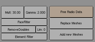
Element Filter (But) This option filters Elements to remove aliasing artefacts, to smooth shadow boundaries, or to force equalized colors for the "RemoveDoubles" option.
RemoveDoubles (But) When two neighbouring Elements have a displayed color that differs less than "Lim", the Elements are joined.
Lim (NumBut) This value is used by the previous button. The unit is expressed in a standard 8 bits resolution; a color range from 0 - 255.
FaceFilter (But) Elements are converted to faces for display. A "FaceFilter" forces an extra smoothing in the displayed result, without changing the Element values themselves.
Mult, Gamma (NumBut) The colorspace of the Radiosity solution is far more detailed than can be expressed with simple 24 bit RGB values. When Elements are converted to faces, their energy values are converted to an RGB color using the "Mult" and "Gamma" values. With the "Mult" value you can multiply the energy value, with "Gamma" you can change the contrast of the energy values.
Add New Meshes (But) The faces of the current displayed Radiosity solution are converted to Mesh Objects with vertex colors. A new Material is added that allows immediate rendering. The input-Meshes remain unchanged.
Replace Meshes (But) As previous, but the input-Meshes are removed.
Free Radio Data (But) All Patches, Elements and Faces are freed in Memory. You always must perform this action after using Radiosity to be able to return to normal editing.