Skinning
Skinning is the fine art of defining a surface by means of two or more profiles. In Blender you do so by preparing as many Curves of the the desired shape and then converting them to a single NURBS surface.
As an example we will create a sailing boat. The first thing to do, in side view (NUM3) is to add a Surface Curve. Beware, add a Surface curve and not a curve of Bézier or NURBS flavour, or the trick won't work (Figure 33).
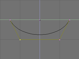
Give the curve the shape of the middle cross section of the ship, by adding vertices as needed with the Split button and, possibly, by setting the NURBS to 'Endpoint' both on 'U' and 'V' (Figure 34).
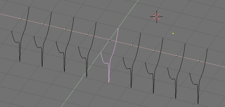
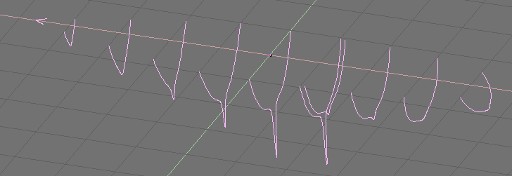
Now duplicate (SHIFT-D) as many times as needed, to the left and to the right, the curve (Figure 35). Adjust the curves accordingly to the section of the ship at different points along its length. Having blueprints helps a lot. You can load a blueprint on the background as we did for the logo design in this same chapter to prepare all the cross section profiles (Figure 36).
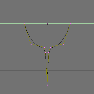
Note that the surface which will be obtained will go smoothly from one profile to the next. To have abrupt changes it is then necessary to place profiles quite close one to the other, as it is the case for the selected profile in Figure 36.
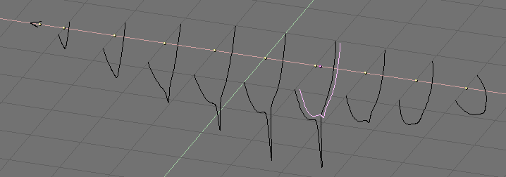
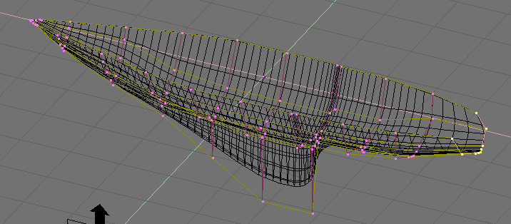
Now select all curves (with AKEY or BKEY) and join them together (by CTRL-J and by answering positively to the question 'Join selected NURBS?'). This will lead to the configuration of Figure 37
Now switch to EditMode (TAB) and select all control points with AKEY; then press FKEY. The profiles will be 'skinned' and converted to a surface (Figure 38). Note that, as it is evident from the first and last profiles in this example, that the cross-sections need not to be coplanar.
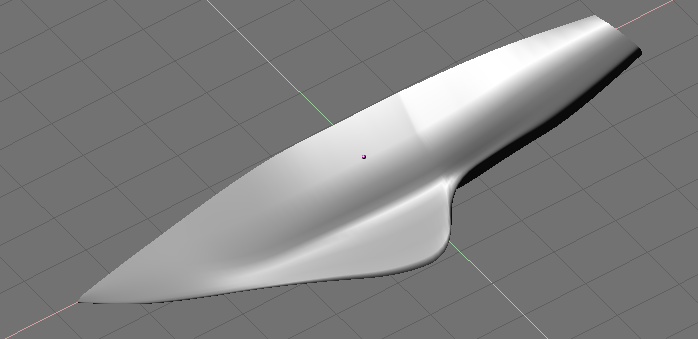
You can then tweak the surface, if necessary, by moving the control points. Figure 39 shows a shaded view.
 | Profile setup |
|---|---|
The only limitation to this otherwise very powerful technique lies in the fact that all profiles must exhibit the same number of control points. This is why it is a good idea to model the most complex cross section first and then duplicate it, moving control points as needed, without adding or removing them, as is done in this example. |