Extrude Along Path
The "Extrude along path" technique is a very powerful modelling tool. It consists of creating a surface by sweeping a given profile along a given path.
Both the profile and the path can be a Bťzier or a NURBS curve.
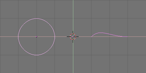
Let's assume you have added a Bťzier curve and a Bťzier circle as separate objects to your scene (Figure 24).
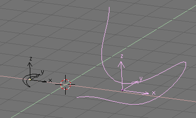
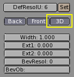
Play a bit with both to obtain a nice 'wing-like' profile and a fancy path (Figure 25). Please note that, by default, Bťziers exist only on a plane, and are 2D objects. To make the path span in all three directions of space, as in the example, you must press the '3D' button in the Curve EditButtons (F9) (Figure 26).
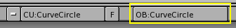
Now look at the name of the profile object. By default it is "CurveCircle" and it is shown on the EditButton toolbar when it is selected. You can change it by SHIFT-LMB on the name, if you like (Figure 27).
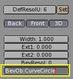
Now select the Path. In its EditButton locate the one named 'BevOb:' and write in there the name of the profile object. In our case 'CurveCircle' (Figure 28).
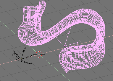
The result is a surface defined by the Profile, sweeping along the path (Figure 29).
To understand the results, and hence obtain the desired effects it is important to understand the following points:
The profile is oriented in such a manner that its z-axis is tangent (i.e. directed along) the Path and that its x-axis is on the plane of the Path; consequently the y-axis is orthogonal to the plane of the Path;
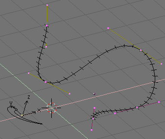
If the Path is 3D the "plane of the path" is defined locally rather than globally and is visually rendered, in EditMode, by several short segments perpendicular to the Path (Figure 30);
The y-axis of the profile always points upwards. This is often a source of unexpected results and problems, as it will be explained later on.
 | Tilting |
|---|---|
You can modify the orientation of the local Path plane by selecting a control point and pressing TKEY. This done, moving the mouse changes the orientation of the short segments smoothly in the neighborhood of the control point. LMB fixes the position, ESC reverts to previous state. |
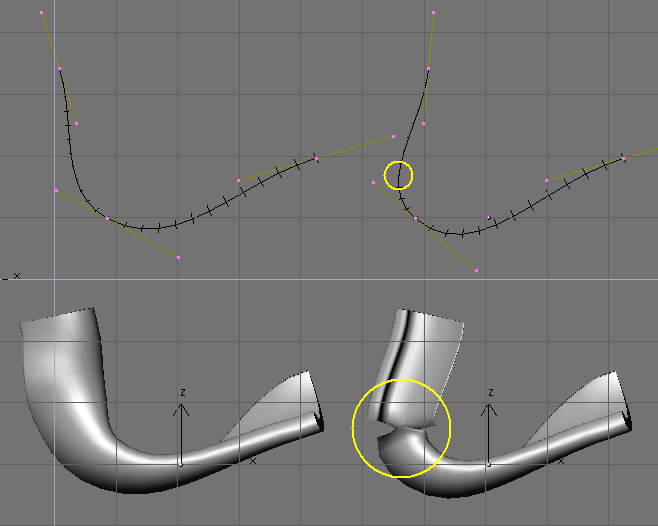
With the y-axis constrained to being upwards, unexpected results can occur when the path is 3D and when the profile being extruded comes to a point where the path bends so that the y-axis of the profile should point downwards. If this occurs, there is an abrupt 180į rotation of the path so that the y-axis points upwards again.
Figure 31 clearly shows the problem. On the left there is a Path whose steepness is such that the normal to the local Path Plane is always upward. On the right a Path where, at the point circled in yellow, such a normal begins to point down. The result of the extrusion presents an abrupt turn there.
The only solutions to this problems are: To use multiple - matching - paths, or to carefully tilt the path to ensure a normal always pointing upwards.
| Changing profile orientation |
|---|---|
If the orientation of the profile along the curve is not the expected one, and you want to rotate it for the whole Path length, there is a better way than tilting all Path control points. You can simply rotate the Profile in EditMode on its plane. This way the profile changes but its local reference doesn't. |