Dupliframes
You can consider Dupliframes in two different ways: an arranging or a modelling tool. In a way, Dupliframes are quite similar to Dupliverts. The only difference is that with Dupliframes we arrange our objects by making them follow a curve rather than using the vertex of a mesh.
Dupliframes or Frame Duplication is a very useful modelling technique for objects which are repeated along a path, such as the wooden sleepers in a railroad, the boards in a fence or the links in a chain, but also for modelling complex curve objects like corkscrews, seashells and spirals.
Modelling using Dupliframes
We are going to model a chain with its links using Dupliframes
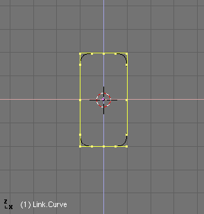
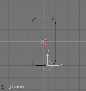
First things come first. To explain the use of dupliframes as a modelling technique, we will start by modelling a single link. To do this, add in front view a Curve Circle (Bezier or Nurbs, whatever). In Edit Mode, subdivide it once and move the vertices a little to fit the link's outline.
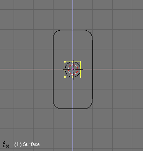
Leave Edit Mode and add a Surface Circle object. NURBS-surfaces are ideal for this purpose, because we can change the resolution easily after creation, and if we need to, we can convert them to a mesh object. It is very important that you do not confuse Curve Circle and Surface Circle. The first one will act as the shape of the link but it will not let us do the skinning step later on. The second one will act as a cross section of our skinning.
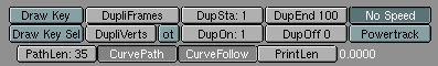
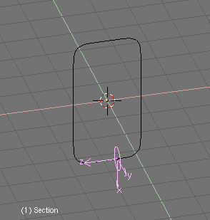
Now parent the circle surface to the circle curve (the link's outline). Select the curve and in the Anims buttons press CurvePath and CurveFollow.
It probably happens that the circle surface will appear dislocated. Just select it and press ALT-O to clear the origin.
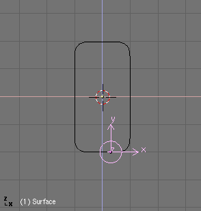
If you hit ALT-A the circle will follow the curve. Now you probably will have to adjust the TRackX,Y,Z and UpX,Y,Z animation buttons, to make the circle go perpendicular to the curve path.
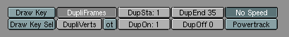
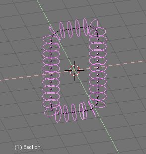
Are you done ?, well, now select the Surface Circle and go to Animation Buttons and press Dupliframes. A number of instances of the circular cross section will appear along the curve path.
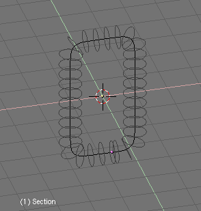
You can adjust the number of circles you want to have with the DupSta, DupEnd, DupOn and DupOff buttons. These buttons control the Start and End of the duplication, the numebr of duplicates each time and also the Offset between duplications. If you want the link to be opened, you can try a different setting for DupEnd.
To turn the structure into a real NURBS-object, select the Surface Circle and press CTRL-SHIFT-A. A pop-up menu will appear prompting "OK? Make Dupli's Real".
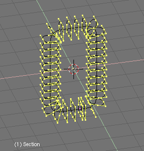
Do not deselect anything. We now have a collection of NURBS forming the outline of our object, but so far they are not skinned, so we cannot see them in a shaded preview or in a rendering. To achieve this, we need to join all the rings to one object. Without deselecting any rings, press CTRL-J and confirm the pop-up menu request. Now, enter EditMode for the newly created object and press AKEY to select all vertices. Now we are ready to skin our object. Press FKEY and Blender will automatically generate the solid object. This operation is called "Skinning".
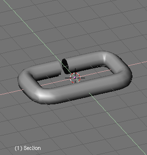
When you leave EditMode, you can now see the object in a shaded view. But it is very dark. To correct this, enter EditMode and select all vertices, then press WKEY. Choose "Switch Direction" from the menu and leave EditMode. The object will now be drawn correctly.
The object we have created is a NURBS object. This means that you can still edit it. Even more interestingly, you can also control the resolution of the NURBS object via the EditButtons.
Here you can set the resolution of the object using "ResolU" and "ResolV", so you can adjust it for working with the object in a low resolution, and then set it to a high resolution for your final render. NURBS objects are also very small in filesize for saved scenes. Compare the size of a NURBS scene with the same scene in which all NURBS are converted (ALT-C) to meshes.
Finally you can delete the curve we used to give the shape of the link, since we will not use it anymore.
Arranging objects with Dupliframes
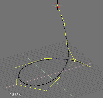
Now we will continue modelling the chain itself. For this, just add a Curve Path (we could use a different curve but this one gives better results). In Edit Mode, move its vertices until get the desired shape of the chain. If not using a Curve Path, you should check the button 3D in the Edit Buttons to let the chain be real 3D.
Select the object "Link" we modelled in the previous step and parent it to the chain curve. Since we are using a Curve Path the option "CurvePath" in the AnimButtons will be automatically activated, however the "CurveFollow" option will not, so you will have to activate it.
If the link is dislocated, select it and press ALT-O to clear the origin. Until now we have done little more than animate the link along the curve. This can be verified by playing the animation with ALT-A.
Now, with the link selected once again go to the AnimButtons. Here, activate the option "DupliFrames" as before. Play With the "DupSta:", "DupEnd:" and "DupOf:" NumButtons. Normally we are going to use "DupOf: 0" for a chain. If using "DupOf: 0" the links are too close from each other you should change the value PathLen for the path curve to a minor value, and correspondingly change the DupEnd: value for the link to that number.
We need that the link rotates along the curve animation, so we have each link rotated 90 degrees respect the preceding one in the chain. For this, select the link and press Axis in the Edit Buttons to reveal the object's axis. Insert a rotation keyframe in the axis which was parallel to the curve. Move 3 or 4 frames ahead and rotate along that axis pressing "R" followed by "X-X" (X twice),Y-Y, or Z-Z to rotate in the local X,Y or Z axis.
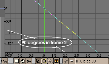
Open an IPO window to edit the rotation of the link along the path. Press the "Extrapolation Mode" so the link will continually rotate until the end of the path. You can edit the IPO rotation curve to make the link rotate exactly 90 degrees every one, two or three links (each link is a frame). Use the "N" key to locate a node exactly at X=2.0 and Y=9.0, which correspond to 90 degrees in 1 frame (since frame 1 to 2).
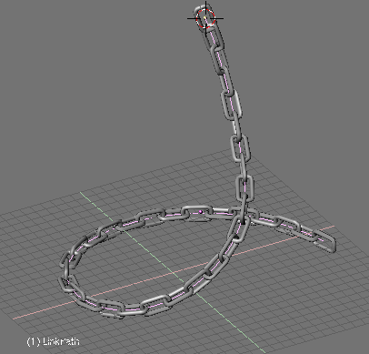
Now we got a nice chain !
More Animation and Modelling
You are not limited to use Curve Paths to model your stuff. These were used just for our own convenience, however in some cases there are no need of them.
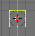
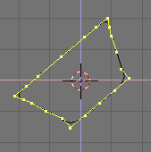
In Front View add a surface circle (you should know why by now). Subdivide once, to make it look more like a square. Move and scale some vertices a little to give it a trapezoid shape.
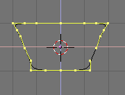
Then rotate all vertices a few degrees. Grab all vertices and displace them some units right or left in X (but at the same Z location). You can use CTRL-K to achieve this precisely. Leave Edit Mode.
From now on, the only thing we are going to do is editing IPO animation curves. So you can call this "Modelling with Animation" if you like. We will not enter Edit Mode for the surface in any moment.
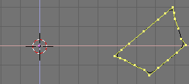
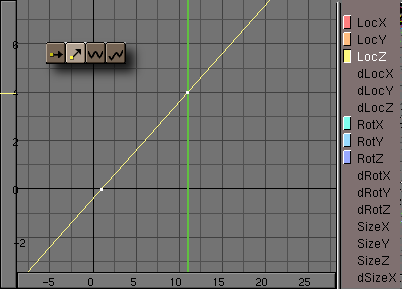
Switch to Top View. Insert a keyframe for rotation at frame 1, go ahead 10 frames and rotate the surface 90 degrees over its new origin. Insert one more keyframe. Open an IPO window, and set the rotation IPO to Extrapolation Mode.
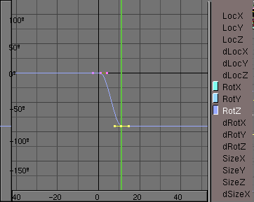
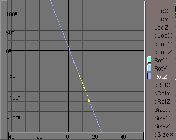
Go back to frame 1 and insert a keyframe for Location. Switch to Front View. Go to frame 11 (just press Cursor Up) and move the surface in Z a few grid units. Insert a new keyframe for Location. In the IPO window set the LocZ to Extrapolation Mode.
Now, of course, go to the Animation buttons and press Dupliframes. You can see how our surface is ascending spirally thru the 3D space forming something like a spring. This is nice, however we want more. Deactivate Dupliframes to continue.
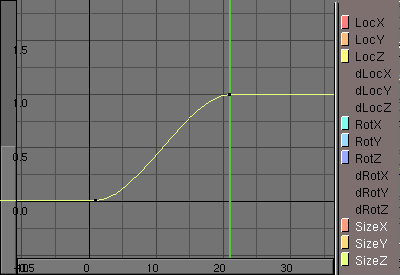
In frame 1 scale the surface to nearly zero and insert a keyframe for Size. Go ahead to frame 41, and clear the size with ALT-S. Insert a new keyframe for size. This IPO will not be in extrapolation mode since we don't want it scales up at infinitum, right ?
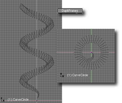
If you now activate Dupliframes you will see a beautiful outline of a corkscrew. Once again the last steps are: Make Duplis Real, Joining teh surfaces, Select all vertices and skinning, Switch direction of normal if needed and leave Edit Mode.
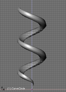
You can see this was a rather simple example. With more IPO curve editing you can achieve very interesting and complex models. Just use your imagination.