EditButtons
EditButtons, general, F9KEY
The settings in this ButtonsWindow visualise the ObData blocks and provide tools for the specific EditModes. Certain buttons are redrawn depending on the type of ObData. The types are: Mesh, Curve, Surface, Text, MetaBall, Lattice, Ika and Camera. This section describes the buttons that appear for nearly all ObData. Later in the text, the buttons are grouped per ObData type. A complete overview of all HotKeys for EditMode is provided in the 3Dwindow section.

The DataButtons in the Header specify what block is visualised. Mesh is used as an example here, but the usage of the other types of ObData is identical.
ME:
Give the current block a new and unique name. The new name is inserted in the list, sorted alphabetically.
Users
If the block is used by more than one Object, this button shows the total number of Objects. Press the button to change this to "Single User". An exact copy is then created.
OB:
Give the current Object a new and unique name. The new name is inserted in the list, sorted alphabetically.
This group of buttons specifies Object characteristics. They are displayed here for ease.
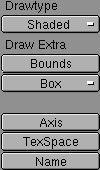
DrawType
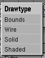
Choose a preference for the standard display method in the 3D window from the list provided. The "DrawType" is compared with the "DrawMode" set in the 3Dheader; the least complex method is the one actually used.
The types, in increasing degree of complexity, are:
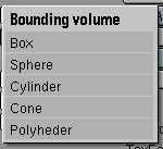
Bounds. A bounding object in the dimensions of the object is drawn.
Wire. The wire model is drawn.
Solid. Zbuffered with the standard OpenGL lighting.
Shaded. This display, which uses Gouraud shading, is the best possible approach to the manner in which Blender renders. It depicts the situation of a single frame from the Camera. Use CTRL+Z to force a recalculation.
The "Draw Extra" options are displayed above the selected DrawType.
TexSpace
The texture space. This can be different from the BoundBox. It is displayed with broken lines.
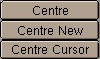
Do Centre
Each ObData has its own local 3D space. The null point of this space is placed at the Object centre. This option calculates a new, centred null point in the ObData. This may change texture coordinates.
Centre New
As above, but now the Object is placed in such a way that the ObData appears to remain in the same place.
Centre Cursor
The new null point of the object is the 3D-Cursor location.
The layer setting of the Object. Use SHIFT+LeftMouse to activate multiple layers.
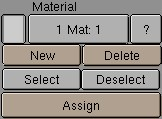
Material indices
Objects and ObData can be linked to more than one Material. This can be managed with these buttons.
1 Mat 1
This button can be used to specify which Material should be shown, i.e. which Material is active. The first digit indicates the amount of Materials, the second digit indicates the index number of the active Material. Each face in a Mesh has a corresponding number: the 'Material index'. The same is true of Curves and Surfaces.
?
In EditMode, this Button indicates what index number, and thus what Material, the selected items have.
New
Make a new index. The current Material is assigned an extra link. If there was no Material, a new one is created.
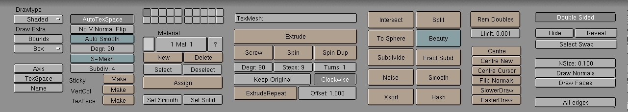
EditButtons, Mesh
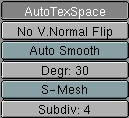
AutoTexSpace
This option calculates the texture area automatically, after leaving EditMode. You can also specify a texture area yourself (Outside EditMode, in the 3DWindow; TKEY), in which case this option is turned OFF.
No V.Normal Flip
Because Blender normally renders double-sided, the direction of the normal (towards the front or the back) is automatically corrected during rendering. This option turns this automatic correction off, allowing "smooth" rendering with faces that have sharp angles (smaller than 100 degrees). Be sure the face normals are set consistently in the same direction (CTRL+N in EditMode).
AutoSmooth
Automatic smooth rendering (not faceted) for meshes. Especially interesting for imported Meshes done in other 3D applications. The Button "Set smooth" also has to be activated to make "Auto Smooth" work. The smoothing isn�t displayed in the 3D Window.
S-Mesh
The S-Mesh option turns a Mesh Object into a S-Mesh. S-Mesh means procedural smooth subdivision of Mesh objects.
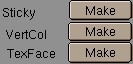
Make Sticky
Blender allows you to assign a texture coordinate to Meshes that is derived from the way the Camera view sees the Mesh. The screen coordinates (only X,Y) are calculated from each vertex and these coordinates are stored in the Mesh. As if the texture is permanently projected and fixed on the Mesh as viewed from the Camera; it becomes "sticky". Use "Sticky" to match a 3D object exactly with the Image Texture of a 3D picture. This option also allows you to create special morphing effects. If the image is already "sticky", the button allows you to remove this effect.
Make VertCol
A colour can be specified per vertex. This is required for the VertexPaint option. If the Object DrawType is "Shaded", these colours are copied to the vertex colours. This allows you to achieve a radiosity-like effect (set MaterialButtons->VertCol ON). If the Mesh is "Double Sided", this is automatically turned off.
Make TexFace
Assigns a texture per face. WIll be automaticly set when you use the UV-Editor to texture a realtime modell.

TexMesh
Enter the name of another Mesh block here to be used as the source for the texture coordinates. Morphing-like effects can then be achieved by distorting the active Mesh. For example, a straight stream of water (as an animated texture) can be placed in a winding river.
Extrude
The most important of the Mesh tools: Extrude Selected. "Extrude" in EditMode converts all selected edges to faces. If possible, the selected faces are also duplicated. Grab mode starts immediately after this command is executed. If there are multiple 3DWindows, the mouse cursor changes to a question mark. Click at the 3DWindow in which "Extrude" must be executed. HotKey: EKEY.
Screw
This tool starts a repetitive "Spin" with a screw-shaped revolution on the selected vertices. You can use this to create screws, springs or shell-shaped structures.
Spin
The "Spin" operation is a repetitively rotating "Extrude". This can be used in every view of the 3DWindow, the rotation axis is always through the 3DCursor, perpendicular to the screen. Set the buttons "Degr" and "Steps" to the desired value. If there are multiple 3DWindows, the mouse cursor changes to a question mark. Click at the 3DWindow in which the "Spin" must occur.
Keep Original
This option saves the selected original for a "Spin" or "Screw" operation. This releases the new vertices and faces from the original piece.
Extrude Repeat
This creates a repetitive "Extrude" along a straight line. This takes place perpendicular to the view of the 3DWindow.
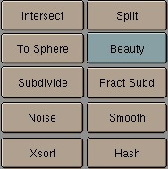
Intersect
Select the faces (vertices) that need an intersection and press this button. Blender now intersects all selected faces with each other.
Split
In EditMode, this command 'splits' the selected part of a Mesh without removing faces. The split sections are no longer connected by edges. Use this to control smoothing. Since the split parts can have vertices at the same position, we recommend that you make selections with the LKEY. HotKey: YKEY.
To Sphere
All selected vertices are blown up into a spherical shape, with the 3DCursor as a midpoint. A requester asks you to specify the factor for this action. HotKey: WKEY.
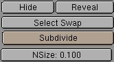
Beauty
This is an option for "Subdivide". It splits the faces into halves lengthwise, converting elongated faces to squares. If the face is smaller than the value of "Limit", it is not longer split in two. Subdivide (But) Selected faces are divided into quarters; all edges are split in half. HotKey: WKEY.
Fract Subd
Fractal Subdivide. Like "Subdivide", but now the new vertices are set with a random vector up or down. A requestor asks you to specify the amount. Use this to generate landscapes or mountains.
Noise
Here Textures can be used to move the selected vertices up a specific amount. The local vertex coordinate is used as the texture coordinate. Every Texture type works with this option. For example, the Stucci produce a landscape effect. Or use Images to express this in relief.
Smooth
All edges with both vertices selected are shortened. This flattens sharp angles. HotKey: WKEY.
Xsort
Sorts the vertices in the X direction. This creates interesting effects with VertexKeys or 'Build Effects' for Halos.
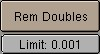
Rem Doubles
Remove Doubles. All selected vertices closer to one another than "Limit" are combined and redundant faces are removed.
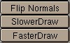
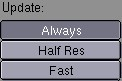
SlowerDraw, FasterDraw.
When leaving EditMode all edges are tested to determine whether they must be displayed as a wire frame. Edges that share two faces with the same normal are never displayed. This increases the recognisability of the Mesh and considerably speeds up drawing. With "SlowerDraw" and "FasterDraw", you can specify that additional or fewer edges must be drawn when you are not in EditMode.
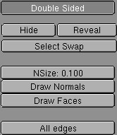
Double Sided
Only for display in the 3Dwindow; can be used to control whether double-sided faces are drawn. Turn this option OFF if the Object has a negative 'size' value (for example an X-flip).
EditButtons, Curve and Surface
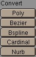
These options convert selected curves.
Bezier
Vertices in a Bezier curve are grouped in threes; the handles. The most frequently used curve type for creating letters or logos.
Nurb
A Nurbs curve is mathematically quite 'pure'. For example: it can be used to create perfect circles.
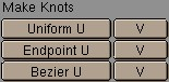
Nurbs curves have knots, a row of numbers that specify the exact curve. Blender offers three pre-sets for this:
Uniform U, V
Sets the knots to create a uniform distribution. Use this for closed curves or surfaces.
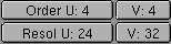
Order U, V
The order is the 'depth' of the curve calculation. Order '1' is a point, order '2' is linear, order '3' is quadratic, etc. Always use order '5' for Curve paths. Order '5' behaves fluently under all circumstances, without annoying discontinuity in the movement.
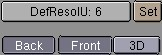
ReslolU, V
The resolution in which the interpolation occurs; the number of points that must be generated between two vertices in the curve.
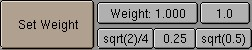
Set Weight
Nurbs curves have a 'weight' per vertex; the extent to which a vertex participates in the interpolation. This button assigns the "Weight" value to all selected vertices.
3D
The curve may now have vertices on each 3D coordinate; the front and back side are never rendered.
These buttons are only drawn for Curve and Font Objects.
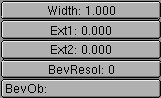
BevOb
The 'bevel' Object. Fill in the name of another Curve Object; this now forms the bevel. For each interpolated point on the curve, the 'bevel Object' is, as it were, extruded and rotated. With this method, for example, you can create the rails of a roller coaster with a 3D curve as the base and two small squares as bevels. Set the values "ResolU" of both Curves carefully, given that this beveling can generate many faces.

EditButtons, Font
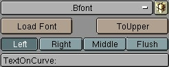
ToUpper
In EditMode, changes all letters into capitals or, if there are no small letters, changes all capitals to small letters.
TextOnCurve
Enter the name of a Curve Object here; this now forms the line along which the text is placed.
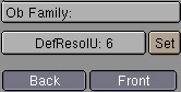
Ob Family
You can create fonts yourself within a Blender file. Each letter from this Font Object is then replaced by any Object you chose, and is automatically duplicated. This means that you can type with Objects! Objects to be considered as letters must belong to the same 'family'; they must have a name that corresponds to the other letter Objects and with the name that must be entered in this button. Important: set the option AnimButtons->DupliVerts ON! For example:
"Ob Family" = Weird.
The Objects that are to replace the letters a and b are called 'Weirda' and 'Weirdb', respectively.
EditButtons, MetaBall
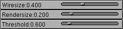
WireSize
Determines the resolution of the MetaBall displayed in the 3DWindow. Be careful with small values, as they use a lot of memory.
EditButtons, Lattice
Meshes and Surfaces can be deformed with Lattices, provided the Lattice is the Parent of the Mesh or Surface.
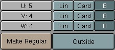
U, V, W
The three dimensions of the Lattice. If a new value is entered here, the Lattice is placed in a regular, standard position.
EditButtons, Ika
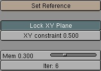
Set Reference
The reference position of an Ika determines the position from which the Ika is calculated towards the user-specified position. This results in a sort of 'memory', a rest mode to which the Ika can always return. A slightly bent form works best as a reference. This position is also evaluated if the IKA has a Skeleton deformation; this is the state in which no deformation occurs.
Lock XY Plane
With this option you are limiting the effector to the XY-plane, to avoid annoying Y-axis flips. This type is default now and much stabler to work with. Known problem: rotating an Ika (with RKEY) is not well defined, so it is better to disable inverse kinematics first with TABKEY and then rotate it.
Mem
This is the extent to which the reference position has an effect on the Ika setting. Set this value to 0.0 to create a completely slack chain.
Iter
The number of iterations of the Ika calculation. To achieve a natural expression, this value can be kept low. During animation or transformation, the Ika then moves to the desired position slowly.
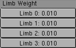
Limb Weight
These numbers give a relationship factor per limb for how stiff or heavy the limb is in relation to other limbs.
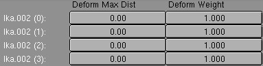
Skeleton Weight
A Skeleton deformation can consist of multiple Ika Objects. These numbers determine the extent to which each Ika contributes to deformation.(Deform Weight) and how far this influence reaches (Deform Max Dist). A "Deform Max Dist" of zero works with an global fall-off, like in older Blender versions.
EditButtons, Camera
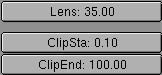
Lens
This number is derived from the lens values of a photo camera: '120' is telelens, '50' is normal, '28' is wide angle.
ClipSta, ClipEnd
Everything that is visible from the Camera's point of view between these values is rendered. Try to keep these values close to one another, so that the Zbuffer functions optimally.
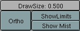
Ortho
A Camera can also render orthogonally. The distance from the Camera then has no effect on the size of the rendered objects.